Introduction
Electric power can be generated by a number of different processes, systems and components; however, most electricity is generated through the use of a rotating electric generator. An electric generator operates on the principle that a small electric current can be generated in a wire by passing it through a magnetic field. By using many wires in a coil, the currents are added to one another to generate usable electric current.
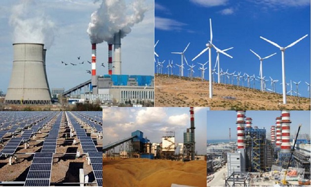
Commercial power generation can be broken down into three categories based upon the energy source used: thermal (coal, gas, and oil), renewable (hydro, biomass, geothermal, solar, and wind), and nuclear. Total generation in 1996 by U.S. electric utilities was 3,077 billion kilowatt-hours. Of the total generation, 68 percent was thermal, 10 percent renewable, and 22 percent nuclear. Coal fired units accounted for 84 percent of the thermal generation or 57 percent of the total. Non-utility genera- tors produced 383 billion kilowatt hours in 1995. Approximately 76 percent of the non-utility generation is thermal and 24 percent renewable. Natural gas ac- counts for 74 percent of the thermal generation or 56 percent of the total non-utility generation.
Consumption of electricity worldwide is estimated at 11.4 trillion kilowatt-hours and expected to grow to 20 trillion kilowatt-hours by 2015. This represents approximately a three percent increase in power consumption.
In a conventional thermal process, a steam turbine converts steam energy into usable, rotational energy to turn the generator. Boilers produce steam to operate the turbine. Windmills, water turbines, internal combustion engines and other motive forces can be used in place of the steam turbine to turn the generator.
Although coal is the most common fuel to fire a boiler in a power plant, natural gas, oil or even biomass can be utilized as fuel to replace the coal to fire the boiler, and the majority of the process remains unchanged. Exhaust gas and ash disposal systems are dependent on the type of fuel being used. Figure 1 provides an overall view of a coal- fired power plant and the power generation process.
This guide offers the reader a general understanding of the major systems in a power plant utilizing a conventional boiler fired by coal, oil, gas or biomass to produce subcritical steam, which drives a steam turbine connected to a generator. A brief discussion of variations of this process such as nuclear, gas turbine, and supercritical plants are also described and covered individually under their own section. Rather than give a complete description of each of these variations, the major differences between them and the conventional thermal processes are explained.

Conventional Subcritical Coal-Fired Power Plant
Actual power generation facilities are very complex and involve numerous processes and components. Steam power plants can be classified as subcritical and super- critical. If a plant operates below the critical point of water (3208.2 psia), it is classified as subcritical.
This section is intended to provide a description of the processes and major components in a subcritical power plant (see Figure 2). Although similar in many ways, the super-critical power plant has some variations that are covered in greater detail in a separate section.
The conventional power generation process is a continuous cycle; therefore, discussion can begin at any point in the cycle. Because each part of the cycle builds upon the previous process in a continuous loop, the entire power generation cycle must be explained before each process becomes clear.
This discussion begins at the condenser. Water from the condenser is heated and the pressure increases through the feedwater system. The boiler adds more heat energy, and the superheated steam expands through a series of turbine blades that turn the generator. The expanded steam exits the turbine to the condenser, and the cycle continues.

Condensate System

Condenser
The condenser operates on the principle that a mass of liquid occupies significantly less space than an equal mass of gas. For example, a pound of steam at 212 F and atmospheric pressure would occupy 26.8 cubic feet. The same pound of steam, if condensed, would occupy only about 0.017 cubic feet. That is a volumetric reduction of almost 99.94 percent. In a condenser, the exhaust steam from the turbine is passed through a heat exchanger where cool water running through tubes condenses steam into a liquid. This reduction in volume forms a vacuum in the condenser. Reducing the pres- sure in the condenser allows the steam from the turbine to condense at a lower temperature. The lower the pressure and temperature that can be achieved in the condenser, the greater the overall efficiency of the plant.
Cooling water is brought into the condenser through tubes and the exhaust steam passes by them. In this manner, the heat is transferred from the steam to the cooling water and the steam condenses and is collected in the ‘hotwell’ to be used again as feedwater. The warm cooling water is then circulated to a cooling tower where it is cooled to near ambient conditions (Figures 3 and 4).
Makeup Water
A power plant is a continuous cycle; therefore, theoretically, very little water should have to be added. In every system, however, leaks and evaporation occur, requiring a small amount of water to be added to the system. This water is referred to as makeup water.
Water Treatment
Impurities in feedwater can cause serious corrosion problems and adversly affect the efficiency and operation of a power plant. Pure water rarely exists naturally; thus, raw water for makeup needs to be treated to reduce contaminants that cause corrosion and leave deposits throughout the system. No water treatment is completely effective in removing impurities. Those impurities not removed from the makeup water prior to entering the system concentrate in the feedwater and boiler. These impurities are often removed in a process referred to as ‘blowdown.’ Blowdown can be either a continuous or intermittent process and involves using a valve to release water from the boiler.
Water contains both dissolved and suspended solids of various types and concentrations, depending upon its source. Suspended solids can be removed by filtration or settling. Dissolved solids cannot be removed by filtration and are in solution with water. Examples of suspended solids include mud, silt, sand, clay, organic matter and some metallic oxides. Examples of dissolved solids include iron, calcium, silica, magnesium and sodium.
If left in the system, dissolved solids form scale on the boiler internal surfaces and reduce heat transfer. This can result in overheating of the tubes and failure or damage of other downstream equipment. Dissolved solids can be removed from the system using a variety of processes including evaporation, ion exchange, reverse osmosis, electrodialysis and ultrafiltration.

Condensate Pump
Condensate collected in the hotwell will be at the same pressure as the condenser (approximately 0.5 psia) and must be pressurized before moving on to the feedwater system. During start-up, little if any flow is circulating through the system. For this reason, it is necessary for the condensate pump to have a recirculation system similar to the main feedpump. In the condensate pump case, however, the water to be recirculated is at significantly lower pressure and tem- perature than the main feedpump. Recirculation prevents overheating and cavitation of centrifugal pumps.
A control valve known as the condensate pump recirculation valve provides the required minimum flow. After
passing through the condensate pump, the condensate enters the feedwater system. In order to make usable energy to turn the steam turbine, water needs to be pressurized and heated until it vaporizes into steam. After vaporizing, the steam temperature is elevated (superheated) to maximize the energy content of the steam and to protect the turbine from water damage. The boiler provides the energy to vaporize and superheat steam. The boiler is also used to reheat steam between turbine sections.

Feed Water System

The feedwater system provides the boiler with water in the proper volume and at the design pressure and
temperature. The feedwater system includes the low and high pressure feedwater heaters, deaerator and
boiler feedpump (see Figure 5). If the feedwater is delivered at the incorrect temperature or pressure, the
boiler tubes and downstream equipment can be damaged. Improper temperatures also adversely affect the
efficiency and reliability of the process. In a typical subcritical plant, the feedwater is delivered to the boiler
at approximately 2400 – 3200 psig and 300 – 500° F. Too low of a flow to the boiler can result in overheating
of the tubes, while too high of a flow can result in wet steam entering the turbine, causing water damage to
the turbine blades.
Boiler Feedpump
Pressurization of the feedwater is accomplished through the use of a boiler feedpump that is commonly steam driven. Large plants may have a smaller motor-driven feedpump for start-ups. Also, smaller power plants may
utilize a motor-driven main feedpump. Boiler feedpumps require a minimum flow to protect against overheating and cavitation. Minimum circulation for the feedpumps is provided by a feedwater recirculation system. The recirculation system diverts the minimum flow from the discharge of the pump back to either the condenser or the deaerator. Because both the condenser and the deaerator are at relatively low pressures as compared to the high discharge pressures of the pump, severe cavitation can be expected in the valve diverting this flow. This valve is referred to as the ‘boiler feedpump recirculation valve,’ ‘feedpump minimum bypass valve’ or ‘automatic recirculation control valve’ and is one of the most severe applications in the power plant. During normal plant operation, sufficient flow is passing through the feedpump to the boiler without any recirculation, so the valve will be closed. Figure 6 is a steam driven, boiler feedpump.

Feedwater Heaters
In the feedwater system, water passes through a series of heaters referred to generically as feedwater heaters, which utilize steam extracted from various stages of the turbine to raise the temperature of the boiler feedwater. The heat energy from the steam is transferred to the feedwater in these heaters through a tube and shell type heat exchanger or through direct mixing of the steam and the feedwater. Feedwater heaters that mix the steam and water are referred to as ‘open’ while those utilizing a tube and shell type heat exchanger are ‘closed.’ A closed type feedwater heater is depicted in Figure 7. Open feedwater heaters serve a dual function of feedwater heating and removing non-condensable gases. The function of removing non-condensable gases is covered in greater detail in the Deaerator section. Feedwater heaters are further categorized as either low or high pressure. The difference between the two is that the low-pressure units are heating water that has not yet passed through the boiler feedpump or the deaerator. High-pressure feedwater heaters are located after the main feedpump and are closed while the low-pressure heaters can be either open or closed. Steam for the low-pressure heaters is commonly extracted from the low pressure section of the turbine. High-pressure heaters are located downstream of the boiler feed pump and utilize steam extracted from the high or intermediate pressure sections.

In closed feedwater heaters, as the steam gives up its heat to the feedwater it loses energy and often condenses. Control valves referred to as ‘heater drain valves’ control the condensate level in each of the
heaters. Condensate from one heater is cascaded down to the next heater. Condensate from the heaters
can be returned to the condenser, deaerator or mixed with the feedwater, depending upon the plant design
(see Figure 8).

Deaerator
After the feedwater leaves the last of the low-pressure heaters, it is directed to a device known as the deaerator to remove the non-condensable gases in the feedwater. The deaerator operates on the principle that hot water can hold considerably less dissolved gases than cold water. Using extraction steam, the feedwater is heated in the deaerator to near saturation temperatures, and the water releases the dissolved gases which are then vented off. The deaerator is actually an open feedwater heater. Feedwater is a combination of makeup water and water condensed from steam that has passed through the boiler and into the condenser. Because the condenser is operated at a vacuum, some atmospheric gases can leak into the system. Also, water holds dissolved gases such as oxygen and nitrogen that are referred to as non-condensable. These gases do not condense at the same temperature as steam, and if they are not removed they can build up in the condenser , causing the pressure to rise. Also, dissolved gases left in the system can lead to corrosion of the boiler and piping. If the pres- sure rises in the condenser, the plant will not run efficiently and the turbine could be damaged.

Boiler
The boiler converts the energy in the fuel to heat and transfers this heat energy to the feedwater, combustion air and steam. Heat transfer in the boiler takes place in the economizer, air heater, boiler tubes, drum, superheaters and reheater.

Economizer
The economizer is a bank of tubes through which the feedwater passes before it goes into the main tube section of the boiler. Heat that is remaining in the combustion gases in the boiler after passing through the tubes, superheaters and reheaters is directed through the economizer. The economizer reduces energy con- sumption and thermal strain on the boiler tubes.
Air Heater
The air heater or ‘pre-heater’ heats the combustion air to the boiler in order to improve efficiency and improve combustion. The air heater is the last heat exchanger mechanism in the boiler before the flue gases are vented. Because the flue gas is relatively low in temperature by the time it reaches the air heater, a large surface area is often required in the air heater to facilitate heat transfer.
Drum
After the boiler feedwater has passed through the economizer, it is directed to the boiler tubes and drum where it finally becomes steam. The drum provides an area where the steam separates from the feedwater. The drum is connected to many sections of tubes that circulate the feedwater in the boiler. These steel tubes are arranged to maximize the exposure to the heat from the boiler. As steam bubbles form, they collect in the drum before passing further on. It is important to keep a constant liquid level in the upper drum to provide the proper quality of steam. Control valves called feedwater regulator valves, control the liquid level in the drum. Requirements for the feedwater can vary greatly so the flow rate to the drum must be constantly adjusted. Modern boilers have high heat rates and if new feedwater is not introduced, they can actually boil dry and damage boiler tubes in a matter of a few minutes.
Superheaters
Superheaters are used to raise the temperature of the steam coming from the drum to the design temperature of the turbine. To understand the reason for increasing steam temperature, one must first understand how the maximum thermal efficiency of a power plant is affected by the maximum and minimum operating temperatures. Energy is proportional to absolute temperature so maximum efficiency can be calculated with:
![]()
Because these temperatures are absolute temperatures, you must add 460 to degrees Fahrenheit to get the absolute temperature in degrees Rankine. As an example, for a plant that operates with a maximum temperature of 500° F and a minimum temperature of 160° F, the maximum thermal efficiency would be:
![]()
This example demonstrates the benefit from operating at higher temperatures and a major reason for adding a superheater. In reality, power plants have significant inefficiency and even the best conventional steam
power plants have an actual efficiency of about 40 percent. The superheater consists of alloy steel tubes through which the steam from the drum passes. These tubes are located in the boiler in the path of the hot gases. As the steam passes through these tubes it is heated to a temperature higher than the saturation temperature it achieved in the drum. In addition to improving the thermal efficiency of the plant, adding a superheater also helps insure that the steam does not condense in the lower pressure stages of the turbine and cause damage. It is not uncommon for the boiler to include two sets of superheaters called the primary and secondary superheaters.
Reheater
In addition to the superheaters, steam is often returned to the boiler to be reheated after it has passed through
the high-pressure or intermediate stages of the turbine. Besides a considerable drop in pressure, steam leaving the high-pressure stages of the turbine has also cooled significantly. By returning the steam to the boiler, the reheater brings the steam temperature back up to nearly the same temperature as it was before entering the high-pressure stage of the turbine. By reheating, the efficiency of the lower pressure stages of the turbine can be significantly improved.
Attemperator
Attemperators are used to control the temperature of the steam to the turbine. Allowing too high of a temperature can cause turbine overheating, while too low of temperature affects plant efficiency and can result in water droplets forming in the lower pressure stages of the turbine. Water droplets will quickly erode the turbine blades. Several types of attemperators are available but most contemporary power plants utilize some type of spray attemperator. Spray attemperators function by adding high purity water to the steam through a spray nozzle located at the throat section of a venturi in the steam line. Attemperators are normally located between the primary and secondary superheaters and also before the reheat superheater. Placing the attemperators in these locations helps protect the turbine from water that may not vaporize immediately upon spraying it into the steam (see Figure 11).

Turbine

The turbine is essentially a complex windmill or fan with many blades that converts the thermal energy of the
steam to useful mechanical energy. Steam turbines in thermal generating plants can range in generating
capacity from 1 megawatt to more than 1,000 megawatts. As high-energy steam passes through the various
stages of the turbine, its energy is converted to rotating the turbine. It is common for a turbine to have both high and low pressure sections with a reheat cycle in between. An intermediate stage can also be included,
which may or may not include an additional reheat cycle. After passing through the high-pressure section of the turbine, the steam may be returned to the boiler reheat superheater to increase the steam temperature before entering the next turbine section. This is done to improve the efficiency of the turbine and to reduce the potential of condensate forming in the lower pressure stages of the turbine. The reheat steam is heated to approximately the same temperature as the superheated steam entering the high-pressure turbine. However, the reheat steam pressure is much lower than that of the main steam. Superheated steam pressures might be as high as 2700 psi while reheat steam pressures might be below 600 psi. Steam is also extracted at various points in the turbine for use in other areas of the plant for heating feedwater, operating auxiliary equipment, and space heating. Figure 2 is an example of a plant employing high, low and intermediate pressure turbines with one reheat cycle. After exiting the low-pressure turbine, the steam returns to the condenser. At this point, one complete cycle in the power generation process has been completed.

Super-critical Power Plants
A variation of the conventional power generation process is the super-critical or ‘once-through’ boiler. Super-critical plants operate at pressures exceeding the critical point of water. The term ‘once through’ comes from the identifying feature of the super-critical boiler which has no drum for the separation of the steam and water. While all super-critical plants are once-through, not all once-through plants are super- critical.
The main difference between a conventional and super- critical boiler is that the super-critical boiler is designed to produce steam at temperatures and pressures higher than the super-critical temperature and pressure of water. Figure 14 is a heat balance for a typical super- critical power plant. Operating in the super-critical region increases thermal efficiency, reduces fuel consumption and produces fewer emissions. Because of the higher operating pressures and temperatures, equipment construction, operation and reliability become even more important factors for super-critical plants.
Once-through boilers lack a drum for steam and water separation and heat storage. For this reason, they have a start-up system that includes either a flash tank or separators. The flash tank or separators serve much the same function as a drum while the boiler is coming up to operating temperature, pressure and flow. Figure 15 shows a simplified schematic of a Babcock & Wilcox Universal Pressure Boiler Bypass System.
After start-up of the once-through boiler, the flash tank is bypassed and flow through the plant is as shown in the schematic pictured in Figure 14. Notice that the schematic now becomes similar to a conventional thermal power cycle except that the pressures and temperatures are higher.


Sliding Pressure Control
A term heard frequently when referring to once-through boilers is “sliding pressure control.” Surplus power generating capacity, and the inclusion of many nuclear plants as base load units increased the necessity of throttling once-through power plants during low demand times. Sliding pressure control was developed as a method of allowing once-through boilers to cycle their load during off-peak hours. Regulating the pressure of the steam entering the turbine controls the generator speed. Turbine control valves, located on the inlet of the turbine, normally perform this function for moderate changes in demand. However, if demand swings often or widely, a different control strategy is necessary to protect the turbine. Flow through a valve can be considered a constant enthalpy (h – btu/lbm) process. By referring to the steam tables it can be easily demonstrated that when the pressure is reduced through a valve, in order to maintain the same enthalpy, the temperature of the outlet steam must also be reduced. This means that large demand swings can result in significant steam temperature changes that can cause turbine damage and reduce the thermal efficiency of the plant. Sliding pressure control allows the turbine load to vary with demand while supplying the turbine with constant temperature steam. This is accomplished by opening the turbine control valve and controlling the turbine with a control valve located between the primary and secondary superheaters. Even though the steam temperature downstream of the sliding pressure control valve may vary as a result of its throttling, the secondary superheater can smooth out the resulting temperature changes of the steam prior to entering the turbine. Figure 16 illustrates normal and sliding pressure control.

Gas Turbines
Gas turbines are often utilized to turn the generator rather than a steam turbine. Due to an abundance of inexpensive natural gas, a relatively easy permitting process, and a short construction cycle, gas turbines have become a very popular way of adding generating capacity. Gas turbines have quick start-up times and as a result are popular for peaking, remote, emergency and reserve power requirements. Gas turbines are available in a variety of sizes and configurations with modern turbines being delivered with generating capacity in excess of 200 MW and firing temperatures exceeding 2000° F. Gas turbines can be designed and built specifically for power generation purposes or may be adapted from other applications. An example of an adapted turbine is the aeroderivative turbine. An aeroderivative turbine is one that was originally designed for aviation use that has been converted for power generation.
Combined Cycle
Often, in order to increase efficiency of a gas turbine, a heat recovery steam generator (HRSG) is utilized to make use of the waste heat in the turbine exhaust to generate steam. The steam generated can then be routed through a steam turbine and associated cycle to generate even more power. In this case, the waste heat from the gas turbine provides the same function as the coal, oil or gas, while the remainder of the process remains relatively unchanged. When a HRSG is utilized, the turbine is referred to as operating as a “combined cycle.” A typical HRSG is illustrated in Figure 21. Gas turbines without heat recovery boilers are called “simple cycle,” while those operating with heat recovery are “combined cycle” (see Figure 22). Valve applications for a combined cycle installation have most of the same engineering challenges and concerns as those found in a conventional fossil-fuel power plant. In addition to the control valves found on the HRSG, the turbine requires valves for fuel control and shut-off. It is not uncommon for gas turbines to operate under a ‘dual fuel’ control scheme that allows the use of either liquid or gaseous fuel. Dual fuel systems allow power generators to utilize inexpensive natural gas when it is available and switch over to petroleum when the natural gas is unavailable or higher in cost than the alternative petroleum fuel. Gas turbines also often use control valves to inject DI (deionized) water or steam for power augmentation or as a means of controlling NOx emissions. Gas turbine control valves are usually specified by the turbine manufacturer and commonly have hydraulic or electric operators. For additional information on gas turbines and associated control valve applications, contact the Flowserve specialist assigned to the specific gas turbine manufacturer.


